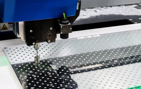
There are many reasons to choose a machine. Here at DEVELOP, we chose our Datron M8 Cube for its capabilities to machine surgically clean parts, with absolutely minute features. However, the strengths that allow that came with the limitation of thread milling. Fortunately, given the right recipes, all of the strengths that drew us to the machine also allowed it to excel at thread milling. So to help others who made the same choice, we’re going to share our recipes for thread milling and how we created them.
To Develop our machining strategies, we designed experiments in four phases to find combinations that will produce threads with high accuracy and precision in 6061 aluminum alloys! These phases tested combinations of tools and parameters for our most commonly machined threads in 6061 aluminum. In Phase One, we tested the end mills that interpolate the minor diameter to gather data on interpolation pitch and feed rates. Phase Two tested the thread mills to find optimal step over, feed rate and programmed major diameter. In Phase Three, we combined the results of the previous phases and performed reliability tests. Lastly, in Phase Four, we tested a tri-form threadmill from Carbide Cutting Tools.
Phase One
Phase one focused on finding helical interpolation parameters for Datron single flute end mills. We selected endmills to machine the minor diameter of threads in a single pass. We tested Datron single flute tools in 2mm, 3mm, and 4mm diameters. These tools are often used on other features we machine, so they are likely already in the magazine.

Phase One – Feed Rate
For the first feed rate test, 1x thread diameter holes, we used Datron’s recommended feed rate as a baseline and increased them by 20% to give us some overhead. We began by slowly increasing the feed rate override from 0% to 100% of the programmed feed rate. As we increased the feed, we monitored machine acceleration, chatter, chip clearing ability, and hole finish. With the smaller holes, machined with the 2mm tool, we found that machine acceleration limited and chip clearance were the primary limiting factors. With the larger holes using the 3mm and 4mm tools, we found the primary limiting factor to be chatter and hole finish. The 2x thread diameter test confirmed these findings. Numerical values are provided below in the chart.

Phase One – Helix Pitch
For helix pitch, we used 10% of cutter diameter as the baseline pitch. Previous testing has shown that 10% is a safe starting point for almost all Datron single flute tools. We then increased the helix pitch by 10% of the cutter diameter four times to achieve a max helix pitch of 50% cutter diameter. While we performed this test, we monitored for the same metric as in the feed rate test. This test showed that the 2mm tool could ramp aggressively, up to 50% of the tool diameter per helix, but only up to 4mm deep. Further longevity testing showed that the aggressive ramp pitch contributed to premature tool wear, reducing that ramp pitch to 20% reduced tool wear significantly while still gaining us a respectable decrease in cycle time. In the 2xD test, we found that after a depth of 4mm, the 2mm tools didn’t clear chips adequately and tended to break. Reducing the helix pitch to 10% tool diameter achieved a stable process for ramping with the longer 2mm tool. The 2xD test also showed that the 3mm and 4mm tools performed better at a lower helix pitch. Refer to the chart below for the final results.

Phase Two
Phase two of the testing focused on finding the optimal parameters for the thread mills. We have two thread mills that machine most of the threads we create, Datron 0068420 and Datron 0068451. These tools allow us to machine M2.5 up to M10, which comfortably covers our threading needs for most of our products.

Phase Two – Thread Mill Radial Depth of Cut
With the lack of rigidity inherent in single-form thread mills in mind, we started our testing by finding the optimal radial depth of cut. We did this by programming a row of holes with different step-over values. This showed that the tools performed best with a very light step-over. To find a more efficient tool path, the parameters were tested again with a single spring pass to find a more efficient tool path. After testing, we found that the tools could give optimal threads with a respectable step-over if a spring pass was applied. Refer to the table below for details.

Phase Two – Thread Mill Feed Rate
The second set of tests in phase two focused on finding the optimal feed rate for the thread mills. With very little published data to pull from, we started with parameters provided by manufacturers of similar tools. This baseline allowed us to produce exceptional threads with excellent finishes but painfully slow. We started increasing the max feed rate 10% at a time until we found a ceiling. For M4 and under the limit was once again machine accelerations, the radius of the helix is simply too small for the M8 to accelerate accurately within. M5 and M6 threads were limited at 1xD by machine acceleration, but at 2xD thread depths, the feed rate had to be reduced to allow the tools to clear chips properly.

Phase Three
We are ready to put it all together now! After evaluating the results from phases one and two, we selected parameters that performed best. We then ran a test to validate the combined parameters of both the end mill and the thread mill. With our assumptions validated, we set up a reliability test.
The test consisted of twenty of each M3, M5, and M6 for a total of 60 holes. These three sizes let us combine the test results for the three sizes of end mill and two sizes of thread mill we used to machine every thread outlined in this test. Even at this stage, we found some parameters that needed to be adjusted. We discovered that Datron single flute end mills will not create a flat bottomed hole when helically boring during this test. The face geometry of the single flute end mill leaves a small domed island at the bottom of a blind hole. The 2mm end mills did not leave a large enough island to cause interference with the thread mill. However, the 4mm end mill did leave a large enough island to interfere with the thread mill, and it was not discovered in prior testing because the threads were not programmed to the bottom of the hole. We decided to maximize thread depth in this final test, programming the thread mill to .1mm above the hole bottom. After raising the programmed depth of the thread mill to avoid that small island, we were able to complete the tests.


Phase Four

Further testing has shown that Tri-form or Miniature Thread mills offer exceptional performance when used in a Datron High-Speed Milling Center. The added rigidity of the larger diameter neck allows for much more aggressive stepovers, up to twice the stepover of a single form thread mill, with all other cutting parameters remaining unchanged. This does come with the compromise of lower tool flexibility, but for applications requiring many threaded holes, the time savings easily justify the cost of these tools.
Many manufacturers of thread mills offer this style of tool, and we encourage you to try them for your application. In our testing of these tools, we’ve found that the speeds and feeds we used with Single-Form thread mills still gave desirable results. However, the increased rigidity of these tools also allows you to increase feed rates but up to 40%.
The larger neck diameter has proven to be a double-edged sword, though. With the ethanol mist coolant used on a Datron HSM Center, we’ve encountered chip clearance issues on deeper threads that we didn’t encounter as readily when using single form thread mills. This appears to be caused by the larger neck diameter not allowing for as efficient mist coolant application in deep holes. This can be countered by utilizing a tool with a longer neck length, which helps to allow ethanol into the hole being thread milled.
Below you’ll find the recipe we’ve developed for the specific brand of Tri-Form Thread Mills we’ve selected as our go-to tools.

Summary
Single point and tri-form threadmills offer unique advantages and that is why we use both in prototype and production. The versatility of the Datron single point thread mill provides flexibility in programming, prototyping, and your tool crib. The tri-form CCT treadmill offers an incredible value of longevity and speed over thousands of the same type of holes.
About the Author:
Matt Moseman leads as President of DEVELOP, with a strong foundation from the Milwaukee School of Engineering, where he earned both a Bachelor’s and a Master’s in New Product Management. Moseman’s career highlights include his pivotal role in founding NodeUDesign, innovating in automation hardware, and driving DEVELOP LLC to the forefront of industrial robotics with a focus on enhancing productivity and efficiency.